I admit I haven't updated in a while but I can use the excuse that I have been busy like everyone else does. Well I have been, between normal work, writing an ATP class for AUGI, getting the RV ready to travel in a few weeks and of course riding the HOG I have been busy.
I do have a few things to post about, first thing is if you are a map user and a member of AUGI I'm teaching a course in the July session so take a look and sign up if you want. It's ATP 134 in case anyone is interested. The first of hopefully many that I'll do unless no one is interested in them.
Second thing I want to pass on is I met up with a fellow named Russell Martin a few weeks ago. Not many people know who Russell is or what he does. I didn't until he E-mailed me a few days before the meet up. But Russell is part of the team at CADAPULT. He has written the book "Digging Into AutoCAD MAP 3D 2005" and a few more, that he dropped off for me to look over and do what ever. Well I have and from my point of view it's an excellent book for anyone that is using AutoCAD MAP. I expect the R2007 version to be out in a few weeks or so. So anyone that need a good book for MAP 3D go get a copy.
Third thing I want to post on is what do my readers of this blog want to learn or need tips on? Post a comment or dig deep enough on the links to find my email addy and send me an email on what you want and I'll try to get some more help out there.
Sunday, May 21, 2006


Wednesday, April 26, 2006
Join lines of text for an Annotation Block Label.
Do you use the annotation blocks to label object in MAP? Do you know you can use the lisp function STRCAT to conation the values together to display as one attribute? In my example I have parcels with object data attached, the values I want to use for an address label are in the HOUSE_NUMBER field and from another field STREET both in a table called Parcel.

Now in the value textbox in the Annotation Text dialog box I use the strcat function like so. (strcat :HOUSE_NUMBER@Parcel " " :STREET@Parcel). What this does is takes the house number value and the street value from the parcel table and joins them together on one line in my labels. Notice the double quotes with a space between them. This is to add a space between the number and street.

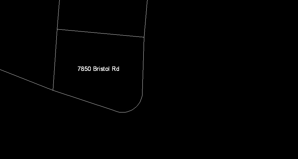
The result after using this is shown below. There are a few others expression evaluators that you can use from doing simple math to converting numbers to strings. Take a look under the topic Expression Evaluators in the Map help file.

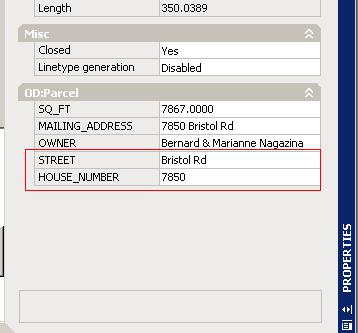
Now in the value textbox in the Annotation Text dialog box I use the strcat function like so. (strcat :HOUSE_NUMBER@Parcel " " :STREET@Parcel). What this does is takes the house number value and the street value from the parcel table and joins them together on one line in my labels. Notice the double quotes with a space between them. This is to add a space between the number and street.

The result after using this is shown below. There are a few others expression evaluators that you can use from doing simple math to converting numbers to strings. Take a look under the topic Expression Evaluators in the Map help file.
Monday, April 17, 2006
Map R2007
Ok the new version is out and has been for a few days. However don't expect to see any tips or "how do" just yet from me here. It will be a while before I can get a copy of the final release. I do have a beta copy but it's a beta and not everything was functional in that version.
If you are a member of AUGI and want to sign up for a map course I may be teaching one for the July ATP session. It will cover importing shape files, labeling and a few alter property queries. You can't sign up yet but I'll keep everyone posted when it opens for enrollment. If you're not a member sign up it's free and a great source of info.
If you are a member of AUGI and want to sign up for a map course I may be teaching one for the July ATP session. It will cover importing shape files, labeling and a few alter property queries. You can't sign up yet but I'll keep everyone posted when it opens for enrollment. If you're not a member sign up it's free and a great source of info.
Monday, April 03, 2006
File Names and Paths
Having trouble importing files into MAP? Check the file name and the path to those files. Map import tools does not handle long file names, file names with spaces or some of the standard characters that other times may work. The civil points import command is really picky at times when it comes to the file name. So if you have trouble creating points from “Section 2 Bubba Subdivision Contour Survey Points.mdb try to rename the file to something like B2CP.mdb.
The shape file import tools doesn’t like long paths to the shape files, so if the files you want to import are in “Z:\GIS\CityData\2006\March\Share\Parcels\Data\Polygons” try making a copy of the needed files in a folder on your local drive “C:\Import”. After the imports are done you can go back and clean up that folder by deleting the shape files.
The shape file import tools doesn’t like long paths to the shape files, so if the files you want to import are in “Z:\GIS\CityData\2006\March\Share\Parcels\Data\Polygons” try making a copy of the needed files in a folder on your local drive “C:\Import”. After the imports are done you can go back and clean up that folder by deleting the shape files.
Sunday, March 26, 2006
GIS for Archies (Architects)
You may ask what does GIS have to do with an architectural firm? Well it's starting to catch on that GIS and AutoCAD MAP can benefit those folks and make some of the every day tasks a little easier. Not only does the cleanup tools in MAP do a better job of removing duplicated objects in a dwg but there are other features than may make having a seat of MAP in the office worthwhile.
Lets look at the "Vicinity Map" that a lot of the firms place on the cover sheet or with a site plan for the project. There was a discussion about the legality of using Yahoo Maps, Google Earth or any other internet mapping application for this. Why not use AutoCAD MAP and make your own. The same data that those mapping programs use is out there for free if you know where to look. Which brings up where can you find this data. First place I would suggest is with your local city or county GIS office. Most large cities have GIS departments now that keep up with all the streets, roads and tax parcels. Other places to look for data is on the internet and at some of the major colleges or universities in your state. Even most states now have a GIS site to share data with others. Some have even extended their data to include things that we as tax payers may never need but other departments in the communities may want to keep up with, for instance fire hydrants and the water pressure at each hydrant.
So what data should you look for? Unless your house in on fire or you need to fill your swimming pool in a hurry you may not care about fire hydrants data. How about locations of schools and shopping centers? Or the bus route that may run right by the site of the new office building you are designing. All that data may be of use to a firm in some way or means. If it is there and free find a way to use it. Any firm that is wanting to get in on the development side of the business can use the information to make better decisions.
Next thing is look at the format the data is in. Most shared data is in ESRI format called shape files, not to be confused with AutoCAD shape files. ESRI shape files consist of at least three files with the extension of shp, dbf, and shx. They will all have the same file name but different extensions. Other format are E00 files, these are another type from ESRI that is in a folder/ directory structure. A few others format you may find are MapInfo (MIF & TAB), Micro station (Dgn), and Spatial Data Transfer Standard(SDTS). Then there are the raster formats out there that may be of use. SID files are popular for images, ER Mapper files (ECW), Jpeg and TIF have geo-reference formats for GIS systems to name a few.
So now that you found some data that you want to use, the next step before you download it is check the "Metadata". Metadata is the info gis users use to tell other users about the data. The create date, the format it is in, how accurate it is, how it was created or collected, how often it is updated and a few other things that may be of use to you. There is no use in down loading a 5 meg file of street data to find out it was created 20 years ago from a hand drawn paper map. So check the metadata before you down load. Most sites will list the metadata right along with the down load button.
So now that you have the data downloaded and figured out how to import it into AutoCAD MAP what is it? Well most of the data is either point, lines/polylines or polygons objects. Points may be a bus stop or a city location on a map, lines(plines) are usually streets or road center lines, and polygons may be the boundary for parks, city limits or footprints to buildings. The data behind all the lines and points like the street names, property owners and etc. are hidden and takes a little work to get into the map but with the right know-how and guidance you can get it. Full time users of MAP will point you in the right direction to get to it and use it as you need, so ask away if you need help.
So what are you waiting for? Get a demo copy of MAP from your dealer, play with it for a few weeks and find some data on the internet, see if it does't help out in the office. A good site to point you in the direction of free data to use is www.gisuser.com click on the data tab and search away it will point you to most any data you will need if it's out there on the web.
Lets look at the "Vicinity Map" that a lot of the firms place on the cover sheet or with a site plan for the project. There was a discussion about the legality of using Yahoo Maps, Google Earth or any other internet mapping application for this. Why not use AutoCAD MAP and make your own. The same data that those mapping programs use is out there for free if you know where to look. Which brings up where can you find this data. First place I would suggest is with your local city or county GIS office. Most large cities have GIS departments now that keep up with all the streets, roads and tax parcels. Other places to look for data is on the internet and at some of the major colleges or universities in your state. Even most states now have a GIS site to share data with others. Some have even extended their data to include things that we as tax payers may never need but other departments in the communities may want to keep up with, for instance fire hydrants and the water pressure at each hydrant.
So what data should you look for? Unless your house in on fire or you need to fill your swimming pool in a hurry you may not care about fire hydrants data. How about locations of schools and shopping centers? Or the bus route that may run right by the site of the new office building you are designing. All that data may be of use to a firm in some way or means. If it is there and free find a way to use it. Any firm that is wanting to get in on the development side of the business can use the information to make better decisions.
Next thing is look at the format the data is in. Most shared data is in ESRI format called shape files, not to be confused with AutoCAD shape files. ESRI shape files consist of at least three files with the extension of shp, dbf, and shx. They will all have the same file name but different extensions. Other format are E00 files, these are another type from ESRI that is in a folder/ directory structure. A few others format you may find are MapInfo (MIF & TAB), Micro station (Dgn), and Spatial Data Transfer Standard(SDTS). Then there are the raster formats out there that may be of use. SID files are popular for images, ER Mapper files (ECW), Jpeg and TIF have geo-reference formats for GIS systems to name a few.
So now that you found some data that you want to use, the next step before you download it is check the "Metadata". Metadata is the info gis users use to tell other users about the data. The create date, the format it is in, how accurate it is, how it was created or collected, how often it is updated and a few other things that may be of use to you. There is no use in down loading a 5 meg file of street data to find out it was created 20 years ago from a hand drawn paper map. So check the metadata before you down load. Most sites will list the metadata right along with the down load button.
So now that you have the data downloaded and figured out how to import it into AutoCAD MAP what is it? Well most of the data is either point, lines/polylines or polygons objects. Points may be a bus stop or a city location on a map, lines(plines) are usually streets or road center lines, and polygons may be the boundary for parks, city limits or footprints to buildings. The data behind all the lines and points like the street names, property owners and etc. are hidden and takes a little work to get into the map but with the right know-how and guidance you can get it. Full time users of MAP will point you in the right direction to get to it and use it as you need, so ask away if you need help.
So what are you waiting for? Get a demo copy of MAP from your dealer, play with it for a few weeks and find some data on the internet, see if it does't help out in the office. A good site to point you in the direction of free data to use is www.gisuser.com click on the data tab and search away it will point you to most any data you will need if it's out there on the web.
Sunday, March 19, 2006
Another week, another post
Well its been week so figure I better write another post. Don't have a tip or how-do this time. Had a few ideas on a couple but haven't had the time to really get into them, maybe next week I'll double up on a couple. I'm off to my states GIS conference tomorrow so maybe I can get some good ideas on what other users are doing or want to do. The thing I hate most about this 2 day conference is it's 99.9% ESRI supported even though there are both ESRI and AutoDesk shops that go. So if anyone that reads this has any connections with the marketing folks at mother Desk put in a few words that we could use some support in this area.
Sunday, March 12, 2006
Points to the Z coordinates from Object Data
Do you need to import an ESRI point file and have the points on the correct “Z” coordinate. The way this can be done in MAP is to import the shp file with Object Data attached, provided the correct elevation is in the data with the shape file. Then attach the “point drawing” to your project and run an alter properties query using the expressions function. This simple example should get you pointed in the right direction.
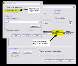
Step one import the shape file and map the data from the file to an Object Data table.
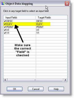
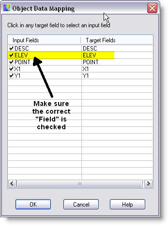
Make sure you check the correct data fields that contains the “Z coordinates” (Elev in this example).
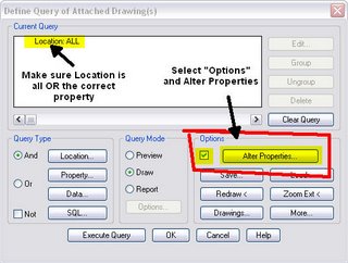
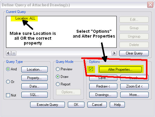
Once the points are imported save and close the drawing. Open a new drawing or your project that you need the points in, attach the drawing you just created. Create an alter-properties query, in this sample I am using “Location ALL” because there is only the points in the drawing. If you already have the points with the OD in an existing drawing you can filter just the layer, points or what you need by the standard query methods.
Select the option for “Alter properties”
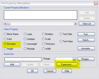
From the Set Property Alterations dialog select Elevations and click on the Expression button.
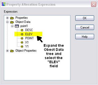
In the Property Alteration Expression dialog expand the Object Data tree and select the field that contains the Z coordinate value. This example uses a field called ELEV.
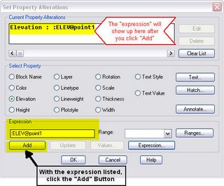
Press OK and it takes you back to the Set Property Alterations dialog. Click on the “Add” button to add the expression to the list.
Click OK in dialog and run the query using the Draw Mode. After the query is ran you can click on a point and verify the new Z coordinate position matches the value from the OD table.
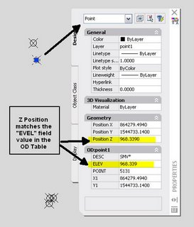
This method of using an Alter Properties Query can also be used to set the elevations for blocks if the value is stored as attributes. For the expression use the properties of the block attribute and get the value from there.
Step one import the shape file and map the data from the file to an Object Data table.
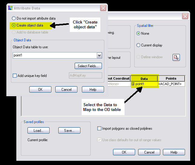
Make sure you check the correct data fields that contains the “Z coordinates” (Elev in this example).
Once the points are imported save and close the drawing. Open a new drawing or your project that you need the points in, attach the drawing you just created. Create an alter-properties query, in this sample I am using “Location ALL” because there is only the points in the drawing. If you already have the points with the OD in an existing drawing you can filter just the layer, points or what you need by the standard query methods.
Select the option for “Alter properties”
From the Set Property Alterations dialog select Elevations and click on the Expression button.

In the Property Alteration Expression dialog expand the Object Data tree and select the field that contains the Z coordinate value. This example uses a field called ELEV.
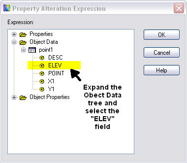
Press OK and it takes you back to the Set Property Alterations dialog. Click on the “Add” button to add the expression to the list.
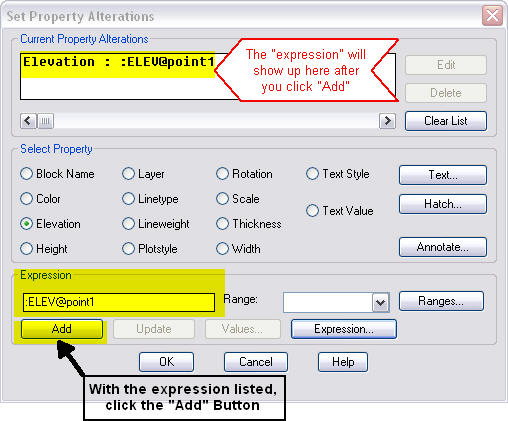
Click OK in dialog and run the query using the Draw Mode. After the query is ran you can click on a point and verify the new Z coordinate position matches the value from the OD table.

This method of using an Alter Properties Query can also be used to set the elevations for blocks if the value is stored as attributes. For the expression use the properties of the block attribute and get the value from there.
Sunday, March 05, 2006
More on Cleanup tools
The trick to using the cleanup tools is knowing what you have (drawing wise) and what you want. As I said in my previous post it's not a one button tool that you run once, or run all the cleanup actions at the same time. I will cover a few more of the Cleanup Actions in this post. We will start with a simple subdivision addition that we want to add to our map(s) as individuals parcels . I assume you know enough about the layer tools and can get the right parcel lines cleaned up using the standard AutoCAD commands. I don't know about your drawings but I get drawings from a number of outside sources that have property lines on 3,4 or even more layers. I'll start with what we have before running the Map Cleanup tools. Looking at the sample we have the parcels as lines, arcs and polylines.
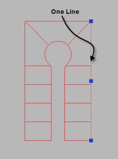
What we want to end up with are closed polylines or Mpolygons that we can attach data to.
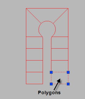
First we want to take a good look at what we have, do the intersections of the lines meet? Were there blocks or shapes at the corners that may have been the Pins or markers on the survey? If there were, we may of deleted them or turned off those layers. The drawings that I get lots of time are like that. The property lines stop short of connecting at the intersection because the civil firm placed more enthusiasms on the corners than on the lines themselves.
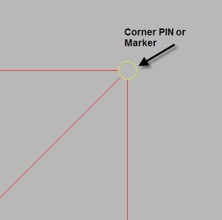
After we delete the PINS we need to snap the lines to the intersection. The Cleanup Action called Apparent Intersection is what you would use. Set the tolerance a little larger than the radius of the PIN symbol. The action tool Extend Undershoots may be used also in some cases. The Extend Undershoots acts like the Extend command in AutoCAD. If there is a line that needs to extend to another line already complete then that works but keep in mind the line you extend to must be there first. Think of the Apparent Intersection action as a super fillet command with an radius of 0.
Another action tool that we need to use is Break Crossing Objects What this does in the sample above is break the lines that run North/South at the intersection of the East/West lines. It's best to use this action after you extend the other line to the intersection. The next Action that we may need to use is Dissolve Pseudo Nodes What this does is connect the two arc polylines at the end of our Cul-de-sac into one polyline. The arc I am referring to is where the reverse curves are at, PRC in civil terms.
Also we want to set a few Cleanup Methods as we run the clean up command. Under the convert options check Line to Polyline and Arc To Polyline, this makes it a lot easier to create the finish polygons so set those two options. The other methods Modify The Orginal Objects, Retain and Create New Orginal,or Delete Orginal and Create New is a matter of choice. Just be sure you specify the correct layer if you create new objects. If you need to keep the orginal ojects or create new objects on a different layers feel free to do so. I only need to modify the objects and have them on the correct layer already so that's the option I use most of the time.
After we run the Cleanup we can create a polygon topology pretty easy and then with that topology we can create Mpolygons with the polygon tools in MAP. After we create the Mpolygons we can delete the topology.
Final words to think about, there may be times when we may use the basic edit tools to cleanup instead of stepping though the cleanup tools. For instance while trying the sample I had trouble breaking part of the arcs in one place that I needed it to break. Instead of wasting the time as to why it didn't break I used the break command a lot faster. Other times I may not of set the tolerance right and missed a few Apparent Intersections, the basic extend command worked faster than going back into the cleanup methods and resetting the tolerances.
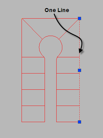
What we want to end up with are closed polylines or Mpolygons that we can attach data to.

First we want to take a good look at what we have, do the intersections of the lines meet? Were there blocks or shapes at the corners that may have been the Pins or markers on the survey? If there were, we may of deleted them or turned off those layers. The drawings that I get lots of time are like that. The property lines stop short of connecting at the intersection because the civil firm placed more enthusiasms on the corners than on the lines themselves.

After we delete the PINS we need to snap the lines to the intersection. The Cleanup Action called Apparent Intersection is what you would use. Set the tolerance a little larger than the radius of the PIN symbol. The action tool Extend Undershoots may be used also in some cases. The Extend Undershoots acts like the Extend command in AutoCAD. If there is a line that needs to extend to another line already complete then that works but keep in mind the line you extend to must be there first. Think of the Apparent Intersection action as a super fillet command with an radius of 0.
Another action tool that we need to use is Break Crossing Objects What this does in the sample above is break the lines that run North/South at the intersection of the East/West lines. It's best to use this action after you extend the other line to the intersection. The next Action that we may need to use is Dissolve Pseudo Nodes What this does is connect the two arc polylines at the end of our Cul-de-sac into one polyline. The arc I am referring to is where the reverse curves are at, PRC in civil terms.
Also we want to set a few Cleanup Methods as we run the clean up command. Under the convert options check Line to Polyline and Arc To Polyline, this makes it a lot easier to create the finish polygons so set those two options. The other methods Modify The Orginal Objects, Retain and Create New Orginal,or Delete Orginal and Create New is a matter of choice. Just be sure you specify the correct layer if you create new objects. If you need to keep the orginal ojects or create new objects on a different layers feel free to do so. I only need to modify the objects and have them on the correct layer already so that's the option I use most of the time.
After we run the Cleanup we can create a polygon topology pretty easy and then with that topology we can create Mpolygons with the polygon tools in MAP. After we create the Mpolygons we can delete the topology.
Final words to think about, there may be times when we may use the basic edit tools to cleanup instead of stepping though the cleanup tools. For instance while trying the sample I had trouble breaking part of the arcs in one place that I needed it to break. Instead of wasting the time as to why it didn't break I used the break command a lot faster. Other times I may not of set the tolerance right and missed a few Apparent Intersections, the basic extend command worked faster than going back into the cleanup methods and resetting the tolerances.
Monday, February 27, 2006
MAP Cleanup Tools
I was asked to post a little something on the drawing clean up tools in MAP so here goes.
First what are they and what can they do. Well just as the name says they can “Clean up” your drawing but if not used right can also mess up a drawing just as easy. The thing you have to remember is the tools are not designed as a one step, push the button tool and magic happens. Not all of the options can be selected at once. I’ll start with the basic one first “Delete Duplicates”. This seems to be everyone’s favorite that does basic mapping or plain CAD in MAP and is the one those users brag about to the “vanilla” users.
Starting with the first dialog it allows you to filter out the object to run the cleanup on either bylayer or feature class if those are in the dwg. You can also use the select method to get only a limited number of objects by selecting just those objects by the standard AutoCAD section method. After you selected the items for cleanup and checked the “Delete Duplicates” from the “Cleanup Actions” you can set a tolerance or other parameters. The tolerance will take into account how close those objects are to each other to delete. The rule to follow here is start with a small tolerance and work your way up to a larger one each time. Setting too large of a tolerance may delete more than you need. The next thing you need to do is select the type of object you want the cleanup to act on. The options are Linear Objects (Lines & Plines), Points, Blocks, Text, and Mtext. You also have options for the rotation of the object and the “Z” coordinates of those objects. If all you need to clean up is text then just select the “TEXT” and MAP will not have to look at all the lines and other types of objects in the map. Hint it will run a little faster and your chances of a crash will be less when you select just the ones you need.
The other option in the “Cleanup Action dialog is the “Interactive” option. This option checked allows you to see each error before it is acted on by MAP.
The next dialog allows you to select the method to use on the action you selected. You can modify the objects, retain the original object and create a new object on a different layer, or create all new objects on a new layer. The second part to this dialog converting the objects to another type of object, lines to polylines for example. If you want all the lines that you selected in the cleanup selection then you would select “Lines to Polylines” and the cleanup will convert the lines for you.
If you select the “interactive” option in the “Cleanup Action” you are given the chance to set the type of marker to use for the errors AutoCAD MAP finds in the cleanup. This can be helpful if you select more than one cleanup action by. If you did not select interactive then this dialog is grayed out and the cleanup is ran with MAP fixing the errors automatically.
I’ll post another entry on more to this cleanup tool as time allows but it gives you a lot more “power” to cleanup and delete duplicated objects than the Express Tool “OverKill”.
First what are they and what can they do. Well just as the name says they can “Clean up” your drawing but if not used right can also mess up a drawing just as easy. The thing you have to remember is the tools are not designed as a one step, push the button tool and magic happens. Not all of the options can be selected at once. I’ll start with the basic one first “Delete Duplicates”. This seems to be everyone’s favorite that does basic mapping or plain CAD in MAP and is the one those users brag about to the “vanilla” users.
Starting with the first dialog it allows you to filter out the object to run the cleanup on either bylayer or feature class if those are in the dwg. You can also use the select method to get only a limited number of objects by selecting just those objects by the standard AutoCAD section method. After you selected the items for cleanup and checked the “Delete Duplicates” from the “Cleanup Actions” you can set a tolerance or other parameters. The tolerance will take into account how close those objects are to each other to delete. The rule to follow here is start with a small tolerance and work your way up to a larger one each time. Setting too large of a tolerance may delete more than you need. The next thing you need to do is select the type of object you want the cleanup to act on. The options are Linear Objects (Lines & Plines), Points, Blocks, Text, and Mtext. You also have options for the rotation of the object and the “Z” coordinates of those objects. If all you need to clean up is text then just select the “TEXT” and MAP will not have to look at all the lines and other types of objects in the map. Hint it will run a little faster and your chances of a crash will be less when you select just the ones you need.
The other option in the “Cleanup Action dialog is the “Interactive” option. This option checked allows you to see each error before it is acted on by MAP.
The next dialog allows you to select the method to use on the action you selected. You can modify the objects, retain the original object and create a new object on a different layer, or create all new objects on a new layer. The second part to this dialog converting the objects to another type of object, lines to polylines for example. If you want all the lines that you selected in the cleanup selection then you would select “Lines to Polylines” and the cleanup will convert the lines for you.
If you select the “interactive” option in the “Cleanup Action” you are given the chance to set the type of marker to use for the errors AutoCAD MAP finds in the cleanup. This can be helpful if you select more than one cleanup action by. If you did not select interactive then this dialog is grayed out and the cleanup is ran with MAP fixing the errors automatically.
I’ll post another entry on more to this cleanup tool as time allows but it gives you a lot more “power” to cleanup and delete duplicated objects than the Express Tool “OverKill”.
Saturday, February 25, 2006
Want those ESRI symbols in your AutoCAD MAP
How many times have you wished the point symbols in the ArcGIS were in AutoCAD MAP. Well they can be with a little work. The symbols in ESRI are nothing but fonts so all you need to do is find out what font file they are in. Go into the properties for the point in ArcMAP and it tells you. In AutoCAD create mtext and import that font using the windows MapChar dialog. Now explode the mtext to lines and arcs or plines. Clean it up a little if needed and create a block from the geometry. Now when you import a ESRI shape file into MAP use that block as the point symbol.
Note: The 3D and the bmp, the ones with color, symbols are not fonts so this tip will not work for them.
Note: The 3D and the bmp, the ones with color, symbols are not fonts so this tip will not work for them.
Friday, February 24, 2006
The World is not Flat
The world is not flat, so why are your maps? I expect that to be asked to a lot more mappers in the next couple of years. Google Earth is 3D so why not the maps that we make. I mean don't we provide the details for developers to show where our assets are at. Just the other day I got in a site plan for a new "project" being build in our service area. They wanted us to show where our electrical lines and poles were at so their engineers could design the services going into the new building. But what happens when those designers start using 3D to their fullest and provide 3D models to the clients. The client may want to know if those same power lines with all the equipment hanging off them will block the view of the half million dollar logo on the side of the building. Will the view from the bosses window be blocked by an ugly rust color steel power pole? Sure we can give them a good look from an airplane flying over head but that's it. It's time for 3D mapping to and for users to make use of it.
Tuesday, January 24, 2006
How accurate does it need to be?
Time and time again I get asked "How accurate it the map?" Well it depends on what you mean by accurate. Like any industry there are tolerances, acceptable or not there are tolerances. Take a set of house plans for instance. The interior walls may be dimension as being 4 -5/8" thick(3- 5/8" stud and two sheets of 1/2" drywall). Now if we got the old micrometer and check an as-built wall we come up with something different. In architecture we allow a 1/16" or even as much as 1/4" tolerances and call it good. So what should we use as a tolerance range in maps?
Saturday, January 14, 2006
So this is my Blog
Been wanting to start one of these for a while just never got around to it. So What's it going to be about, you ask? Well Map AutoCAD MAP software for one. Seems to be a lack of them to it out there now so why not? Maybe some personnal options about the world and the people living on it. But for now just this short posting. Check back later and see if I added anything of use or whatever.
Subscribe to:
Posts (Atom)