This post will be a quick walk-thru on doing it with some screen shots to help you. To start bring in the DEM as a surface.
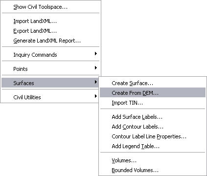
From the pull-down menu under "Civil-Surface-Create From DEM"
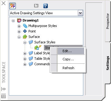
Browse to where the DEM file is located and select it. In a matter of seconds a new surface is created in MAP. Zoom extends and all you may see is a yellow rectangle. The reason you do not see anything is you may not have the styles for the surfaces set to display the objects(contours). The default display for civil surfaces in MAP is to show the border only for 2D display and triangles for 3D display. Open up the Civil Toolspace and click on the “Settings” tab. Expand the surface tree to show the Surface Style Standard. Right click on the standard style and click on edit.
The Style editor dialog will open, for that surface style. The first thing we need to tell MAP 3D is the contour intervals we want it to display. Click on the Contour tab at the top then expand the tree under Contour Intervals.
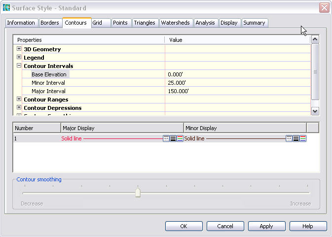
Set the Minor Interval to 25.00' and the Major Interval to 150.00'. Keep the Base Elevation at 0.00'.
Next click on the Display tab so MAP 3D knows will know how we want them displayed.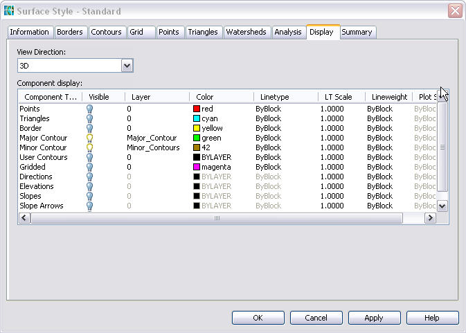
In the View Direction select 3D. Set the Triangles as invisible and Major Contours & Minor Contours as Visible by clicking on the light bulb icon. Next put the contours on their own layers by clicking under the layer for each and select a layer or create a new layer for each. Next you can check that the same settings are there under the View Direction for 2D by switching the 3D to 2D in the View Direction list box. Click apply and OK.
Map takes a few minutes to create and display the contour lines. They should be at the intervals you set and displayed by the color specified in the style editor not by the layer color. Now that you have the contours displayed you may notice they are not polylines but a single object. A Civil object at that, so we need to convert them into polylines to export to a shp file.
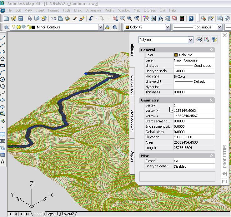
To convert them the first thing I like to do is change my view of them to a 3D view. Using the standard AutoCAD view menu switch to a 3D view (SW Isometric). After MAP rescans the surface you should see that the contours are at the correct elevations. This is a good tip to verify that the DEM was converted to a surface and displays the contours as you wanted. Then next step is to Export the surface to a AutoCAD dwg.
Under the Civil menu, select Civil Utilities>Export to AutoCAD>2004 format.

Save the exported dwg to the folder of your choice. After the export is complete open the dwg that you just created. It should be in the same 3D view as the surface when you exported it, again this is a tip to check and see that you have what you need for the shp file. There is no need to change the view in the new dwg. If you select a contour line, you will notice it is a polyline on the layer you set in the style editor and at the correct elevation.
Now you have the correct objects to Export to a ESRI shp file. When you export it you can export the layer and elevations from the properties to include those in the shp file data.
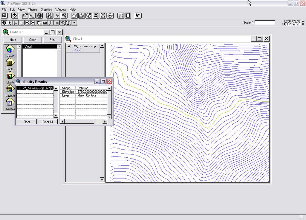
As you can see the contours lines with the elevations and layers are there in a ESRI table so anyone can now use the DEM file as contours in their GIS system.
Note this example was done using Map 3D 2006, the civil tools in Map 3D 2007 are different but I 'll try to post the how-do with R2007 in a few weeks.
An another item to be aware of, when you set the value for the contour intervals keep in mind the smaller the intervals the more there are and the bigger the file becomes then the longer it takes to rescan and redraw the surface.